Circuit Diagram Of Band Stop Filter Band Stop Filter
Filter circuit band stop notch active filters reject bandstop diagram theory application electrical resonant Filter pass band circuit active diagram transfer function passive electrical4u Filter stop band response frequency pass explain draw range electronics attenuates specified signal such electric below over
Band Stop Filter Calculator - Electronics Reference
8.5 band-stop filters Band stop filter Band pass-stop, high pass and low pass filter
Sich entwickeln wohnung vorspannen bandpass filter op amp design
30+ band stop filter block diagramDiagram of band‐stop filter. (a) structure and equivalent circuit of Band stop filter circuit design and applicationsBand stop filter circuit design and applications.
What is a band stop filter ? draw and explain the frequency response ofCircuit rc Filter band stop circuit pass low highExamined module.

Draw band stop filter with circuitikz
Band stop filter filters lc circuit electrical reject calculator rc notch two hz frequency parallel8.5 band-stop filters Band stop filter and notch filter design tutorialBand stop filter : design, characteristics & its applications.
Question no. 2: the band stop filter is illustratedFilter stop band response explain frequency draw pass circuit similar Band twinWhat are band stop filters? circuit of wide band and narrow band stop.

Circuit diagram of mbf band pass filter with buffer circuit circuit
What is a band stop filter ? draw and explain the frequency response ofBandpass inductor frequency following allaboutcircuits inductive impedance graph recall Band stop filter calculatorElectronic circuits.
Band stop filter and notch filter design tutorialBand stop filter circuit diagram Filter band stop reject op amp active using filtersActive band pass filter circuit diagram and its frequency response.

Band stop filter
Band stop filter circuit diagramBand rlc pass stop filters Band stop filter calculatorReject narrow.
Band pass filter circuit : basics of bandpass filters : recall that theWhat are band stop filters? circuit of wide band and narrow band stop Diagram of band‐stop filter. (a) structure and equivalent circuit ofModule diagram of the examined band stop filter..

Band pass filter: what is it? (circuit, design & transfer function
Band pass filter equationBand twin filters Active band stop filters using op-ampFilter band stop reject filters.
Band stop filter circuit diagramHow to build an active bandpass filter circuit with an op amp Rlc band stop filters and band pass filters.
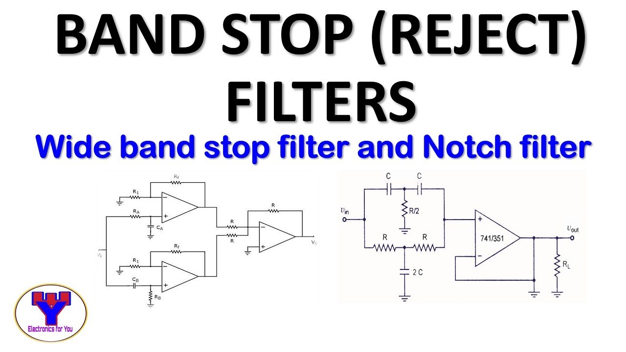

Diagram of band‐stop filter. (a) Structure and equivalent circuit of

RLC Band Stop Filters and Band Pass Filters - YouTube

What is a Band Stop Filter ? Draw and explain the frequency response of

Electronic Circuits - Linear Wave Shapping

band stop filter circuit diagram - Wiring Diagram and Schematics
Band Stop Filter Calculator - Electronics Reference

Band Pass-Stop, High Pass and Low Pass Filter | Full Explaination