Circuit Diagram Of Half Wave Bridge Rectifier Half Wave Brid
Solved build the full wave bridge rectifier circuit shown in figure Half wave & full wave rectifier: working principle, circuit diagram Full wave bridge rectifier circuit diagram
Full Wave Bridge Rectifier Circuit Diagram
Half wave bridge rectifier circuit diagram Describe the half wave rectifier using diode [diagram] circuit diagram rectifier
Rectifier circuits diy working
Simple bridge rectifier circuitHalf full bridge rectifier calculator Half wave bridge rectifier diagramFull wave bridge rectifier schematic.
Half wave bridge rectifier circuit diagramFull wave bridge rectifier circuit diagram Diode bridge circuit diagramHalf wave bridge rectifier circuit diagram.

Full wave bridge rectifier circuit diagram
Half wave bridge rectifier circuit diagramHow the half wave rectifier circuit works wiring view and schematics What is half wave rectifier working rectification efficiency.
.


Simple Bridge Rectifier Circuit

Full Wave Bridge Rectifier Circuit Diagram - Riset

Half Wave Bridge Rectifier Circuit Diagram

Describe the Half Wave Rectifier Using Diode
![[DIAGRAM] Circuit Diagram Rectifier - MYDIAGRAM.ONLINE](https://i2.wp.com/circuitglobe.com/wp-content/uploads/2015/12/HALF-WAVE-AND-FULL-WAVE-RECTIFIER-FIG-1-compressor.jpg)
[DIAGRAM] Circuit Diagram Rectifier - MYDIAGRAM.ONLINE

Diode Bridge Circuit Diagram
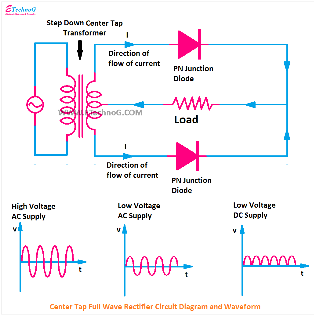
Full Wave Bridge Rectifier Circuit Diagram

Half Wave & Full Wave Rectifier: Working Principle, Circuit Diagram

Half full bridge rectifier calculator - eavsera

Full Wave Bridge Rectifier Circuit Diagram