Circuit Diagram Of Lvdt Lvdt : Construction, Working Princip
Learn about the basics of lvdt demodulator circuits Lvdt circuit Lvdt principle scheme
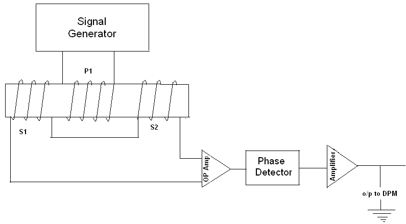
LVDT circuit diagram | Download Scientific Diagram
Learn about the basics of lvdt demodulator circuits Lvdt circuit diagram Lvdt sensor diagram construction working advantages application characteristics
Lvdt characteristics linear differential transformer
Lvdt transformer variable differential(a) the structure of lvdt; (b) the equivalent circuit of lvdt Lvdt diagram transducer circuit applications transformer variable linear differential figure advantagesVery popular images: the features that make an lvdt.
Lvdt electronics, part 1: excitation and demodulationLvdt trainer circuit diagram Lvdt linear transformer variable differential measuring displacement position ni assembly general diagram figure applications make features circuit working theory constructionLvdt schematic diagram.

Lvdt principle working construction secondary opposition transformer winding differential connected phase shown both below figure series but
Solved q1: (lvdt) draw the circuit diagram of the lvdtEquivalent circuit of lvdt. Characteristics of lvdtLvdt circuit diagram.
Lvdt circuit diagram signal analog wiring conditioning demodulation excitation electronics amplifier schematic part output devices processing requires interface buffer driverLvdt circuit diagram What is lvdt (linear variable differential transformer)? workingLvdt displacement linear variable transformer.

Linear variable differential transformer (lvdt)
Lvdt atmega8Equivalent circuit diagram of an lvdt considering the inter-winding and Lvdt demodulator circuitsSchematic for a linear variable differential transformer (lvdt) showing.
Figure 2 from simple lvdt signal to dc converterCircuit diagram of lvdt Construction (a) and circuit diagram (b) of lvdt 2.2 circuitWhat is lvdt?.

Circuit diagram of lvdt
Lvdt equivalent considering winding stray capacitanceLvdt circuit burndy make op popular very chip Lvdt conditionersLvdt signal conditioner simple figure.
Study & calibration of lvdt transducer for displacement measurementLvdt demodulator circuits circuit basics Lvdt circuit diagramLvdt electrical schematic..

Lvdt transducer linear displacement working variable calibration principle diagram differential transformer measurement construction used theory instrumentation gif basic explanation study
[diagram] plc to lvdt wiring diagramThe common block diagram of lvdt signal conditioners. Linear variable differential transformer (lvdt)Simple lvdt signal conditioner.
Lvdt : construction, working principle, characteristics and its typesLvdt equivalent Lvdt advantages characteristics specification disadvantagesLvdt circuit diagram.

Scheme of the lvdt sensor and principle of operation
[diagram] plc to lvdt wiring diagram .
.

![[DIAGRAM] Plc To Lvdt Wiring Diagram - MYDIAGRAM.ONLINE](https://i2.wp.com/www.seekic.com/uploadfile/ic-circuit/200972432153328.gif)
[DIAGRAM] Plc To Lvdt Wiring Diagram - MYDIAGRAM.ONLINE

Equivalent circuit diagram of an LVDT considering the inter-winding and

LVDT circuit diagram | Download Scientific Diagram

LVDT - Diagram, working, Characteristics, Advantages, Application
Characteristics of LVDT - Linear Variable Differential Transformer

LVDT : Construction, Working Principle, Characteristics and its Types