Circuit Diagram To Control 3v Electric Motor Troubleshooting
Three phase motor wiring Motor control three circuits electric troubleshooting starting circuit starter phase basic electrical autotransformer used main after hardwired time voltage typical Relays reversing circuits constructed starters interlocked
Single Phase Ac Motor Speed Control Circuit Diagram - General Wiring
How to read motor control schematics Electrical motor circuit wiring diagrams How to build a 3 phase brushless bldc motor driver circuit
3 phase motor diagram
Single phase ac motor speed control circuit diagram3 phase motor wiring installation diagrams Power circuit diagram of motor3 phase wiring diagram.
Three phase motor control circuit diagram12v to 3v converter circuit diagram Three-phase motor control circuit diagram pdfTroubleshooting three basic hardwired control circuits used in starting.

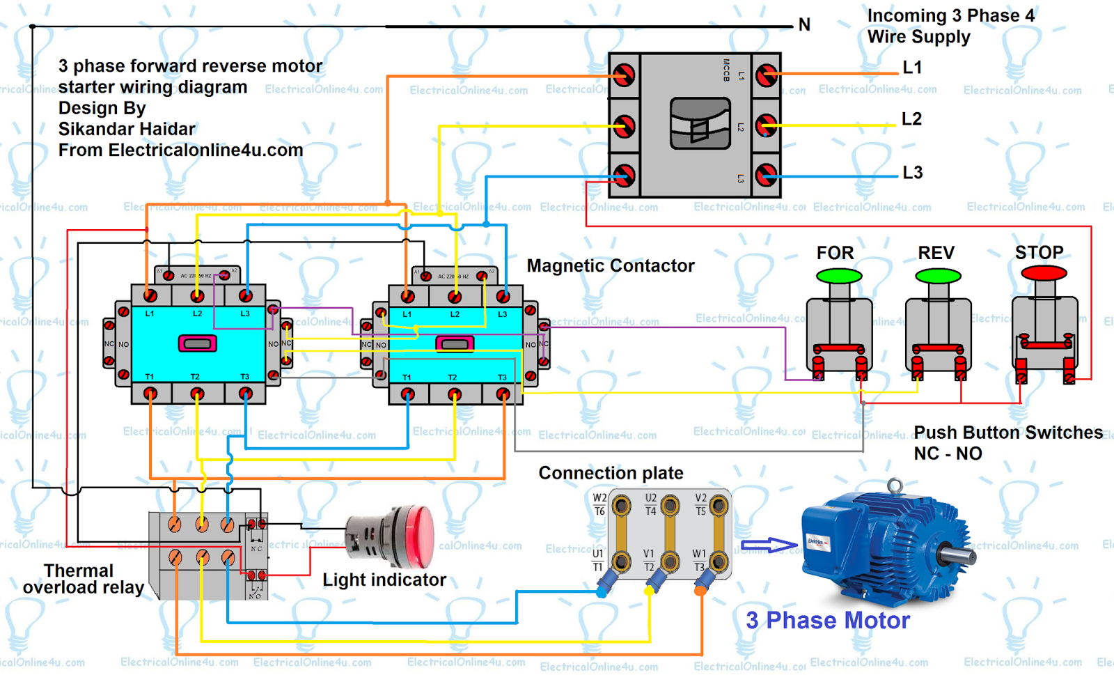
Control circuit diagram 3 phase motor
3 phase motor control panel wiring diagram3 phase motor control circuit diagram Introduction to basic three-phase motor control circuits3v to 12v converter circuit diagram.
Induction circuits triac pwm moc nec iec[diagram] electrical motor control wiring diagrams Wiring control starter[diagram] three phase motor control circuit diagram.


Three-phase Motor Control Circuit Diagram Pdf

Single Phase Ac Motor Speed Control Circuit Diagram - General Wiring
3 Phase Motor Diagram

Troubleshooting three basic hardwired control circuits used in starting
![[DIAGRAM] Electrical Motor Control Wiring Diagrams - MYDIAGRAM.ONLINE](https://i2.wp.com/maintenanceskill.com/wp-content/uploads/2018/11/3-Phase-Motor-Control-Circuit.jpg)
[DIAGRAM] Electrical Motor Control Wiring Diagrams - MYDIAGRAM.ONLINE

3 Phase Motor Control Circuit Diagram

12v To 3v Converter Circuit Diagram

Introduction to Basic Three-Phase Motor Control Circuits - Technical

How To Build A 3 Phase Brushless Bldc Motor Driver Circuit | Images and

How To Read Motor Control Schematics